Derivation of a complete set of in-orbit RSRFs is needed to obtain an optimal flux calibration accuracy. However, this calibration is still ongoing. Until this has been done, the RSRFs measured in the lab have to be used for most bands. For bands 1a and 2a, a correction of the overall shape was applied to compensate for the leakage problem previously mentioned. This correction was done by polynomial fitting of in-orbit and lab data and multiplying the lab data with the ratio of the two fits.
For OLP V6.1 the Cal-G 25_x files containing the RSRF's were updated leading to a significantly improved calibration of the spectra. The few problems found in the new calibration files were, however, almost always present in the previous set of RSRF's.
These problems were:
If the dark current subtraction was not correct, and therefore incorrect offset correction applied, the Derive-AAR respcal step (which is a gain correction) can introduce incorrect shapes of the continuum or false features.
A way to check if the dark current subtraction has been done correctly is to overplot the AAR spectrum after respcal with the RSRF and checking to see if any small residual RSRF features remain.
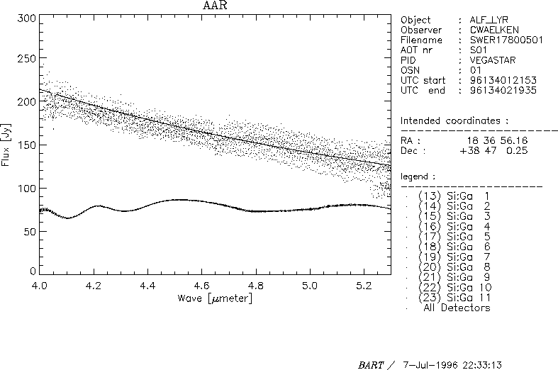
Examples are given in figures 6.2 and 6.3.

Figure 6.2: The dark subtraction has been done properly. There is no
agreement between the features in the RSRF (solid line below the spectrum) and
the spectrum. The solid line through the datapoints of the spectrum is a model
atmosphere.

Figure 6.3: The dark subtraction has not been done properly. If we
overplot the RSRF (solid line through the spectrum), we see that the features
in the spectrum are not real. Also the slope of the spectrum is not real
(compare to the model atmosphere printed above the spectrum) Flatfielding the
AAR might help to decrease the scatter between the different detectors, but it
will never correct for the real problem.
The following section gives an overview of the RSRFs as seen in the lab versus the RSRFs as measured in orbit. These graphs can be used to determine in which regions the RSRF calibration is more uncertain. This is mostly at some band edges. They help us to understand inconsistencies as in figure 6.4.
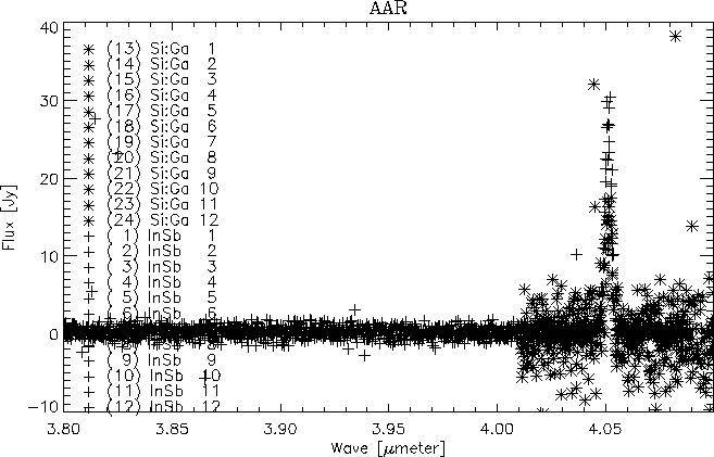
After rebinning the spectrum shown in this figure, the continuum level in band 1e will be in agreement with band 2a . However, the line flux at 4.05 microns will be about 30% lower. One should keep in mind that we're talking about a continuum which is virtually zero - errors in a gain correction (like dividing by RSRF or the absolute flux conversion) will be almost invisible on the continuum, but very clear in the line fluxes.
This means one has to be careful when interpreting line fluxes of spectra with a zero-continuum: if the line is in a region where the lab RSRF is different from the in-orbit RSRF, the flux of the line is less accurate. Thus in the example shown in figure 6.4, the line flux in band 1e has to be believed.
It should be noted that (1) these problems are less likely to occur with spectra with a high continuum because the errors in the gain correction will be applied to the continuum as well (thus the line/cont ratio will be correct) and (2) the differences in line fluxes in the example do not represent the current uncertainties of the RSRF flux calibration in that region: this observation was an early PV observation with the AOT logic not fully optimised.

Figure 6.4: The 4.05 micron line as seen in bands 1e (+ symbols) and 2a
(* symbols)
In detector band 3 large fringes are present. These fringes can shift with the position of the source in the slit. A small mispointing (within the specs of ISO) can shift the fringes over 1/4 of their period. Before measuring line fluxes of unresolved lines in this band, it has to be checked if the fringes in the SPD are in phase with the fringes in the RSRF. If not, the fluxes of unresolved lines in band 3 might be off by 25% since the relative size of the fringes is about 50%.
This also means line fluxes measured with fast AOT 1 observations that cannot resolve the fringes in band 3 are only reliable for less than 25%.
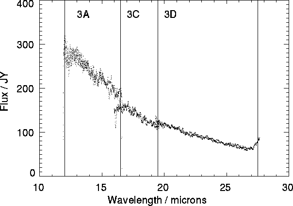
Band 3D suffers from leakage around 27 ![]() . Figure 6.5 shows
band 3 data of an object with flux falling towards longer wavelengths. The
slight increase in the flux seen in band 3d from about 27
. Figure 6.5 shows
band 3 data of an object with flux falling towards longer wavelengths. The
slight increase in the flux seen in band 3d from about 27 ![]() onwards is not
real but is due to leakage from approximately 13
onwards is not
real but is due to leakage from approximately 13 ![]() . This leakage is of the
order of 10% and will primarily affect objects with flux falling sharply
towards long wavelengths.
. This leakage is of the
order of 10% and will primarily affect objects with flux falling sharply
towards long wavelengths.

Figure 6.5: Band 3 data showing the leak around 27 microns
Spurious features may be present in band 2C (7 to 12 microns) that should not be mistaken for actual spectral features from the object of interest. This warning is based on a small sample of observations, and its conclusions should be treated as preliminary at this stage.
Band 2C features are a collection of ubiquitous spectral `lines' in emission and absorption seen between 7 and 12 microns (SWS Band 2C). An example of these features is shown in Figure 6.6, the normalized flux of an AOT1 speed 1. Also plotted is the Relative Spectral Response Function (RSRF) of Band2c.
The features occur at:
9.35 microns in absorption with a FWHM: 0.3 microns
10.05 microns in emission with a FWHM: 0.1 microns
11.05 microns in emission with a FWHM: 0.1 microns

Figure 6.6: SWS spectrum showing spurious features
Forty-three Band 2C spectra were collected from 9 observers in order to find trends in the strength of the features. The spectra are from both carbon and oxygen rich objects which are, in turn, stellar and nebular in origin. Since a rather broad wavelength range is required, only data from AOT SWS01 observations was used. This does not preclude the features being present in the data from other AOTs.
Table 6.1 shows a summary of the 43 sources in the sample with at least one feature. The peak wavelengths, FWHM and Percent of continuum levels (``% Cont'', negative meaning absorption, positive emission) are median values in the sample. Also listed are the minimum and maximum values for each parameter that were seen in the dataset. Some of the spread is due to noisy data and the difficulty of measuring the continuum and width of a line.
| Feature | # | Peak | (Min, | Max) | Median | (Min, | Max) | % Cont | (Min, | Max) |
| Waveln. | FWHM | |||||||||
| 9.35 | 36 | 9.26 | ( 9.2 , | 9.4 ) | 0.295 | (0.029, | 0.482) | -7 | (-14, | 1) |
| 10.05 | 30 | 10.07 | ( 9.96, | 10.10) | 0.094 | (0.017, | 0.280) | 3 | ( -5, | 11) |
| 11.05 | 37 | 11.05 | (11.01, | 11.11) | 0.090 | (0.050, | 0.180) | 6 | ( 4, | 15) |
The summary for the absence of features is shown in Table 6.2. We have listed the number of sources that do NOT show a feature and the continuum level where we expect the feature to be. In general the absence of a feature correlates with the continuum strength. Of the sources that do not show one of of the features, at least 2/3 of these have continua below 100 Jy. Again, this may be an indication of the difficulty in measuring the features.
| Feature | Number | Median Cont | (Min, | Max) |
| (Jy) | ||||
| 9.35 | 7 | 63 | (20, | 4200) |
| 10.05 | 13 | 46 | (14, | 430) |
| 11.05 | 6 | 18 | (12, | 115) |
The remaining sources that have high continua but do not show a feature remain a puzzle. Of the high continuum sources (;SPMgt;100 Jy), 2 do not show the 9.35 micron feature, 3 do not show the 10.05 and 1 does not show the 11.05 feature.
Since we did not specifically ask for sources that did not show any features, we cannot draw any conclusions about these sources.
From the 43 sources we find the following:
There are a number of arguments why these features are not astronomical:
However, the absence of features in some spectra clouds the problem greatly. If these features are introduced in the RSRF, then we must explain what is happening in the sources without the features. Again there are a number of possibilities:
From the small number of observations studied the preliminary conclusions on these spectral features are that they appear in all types of objects and are a constant fraction of the source continuum, roughly 5%. At this time, the best explanation is that the features are introduced by the RSRF and are not astronomical in origin.
While only AOT 1's have been checked, these features have been seen in the data from other grating AOT's.
These conclusions should be viewed as preliminary until a more complete investigation is carried out.