This page shows images of the WIRE cryostat. They were taken during testing by Lockheed-Martin in Northern California. Click on the images for a larger version
|
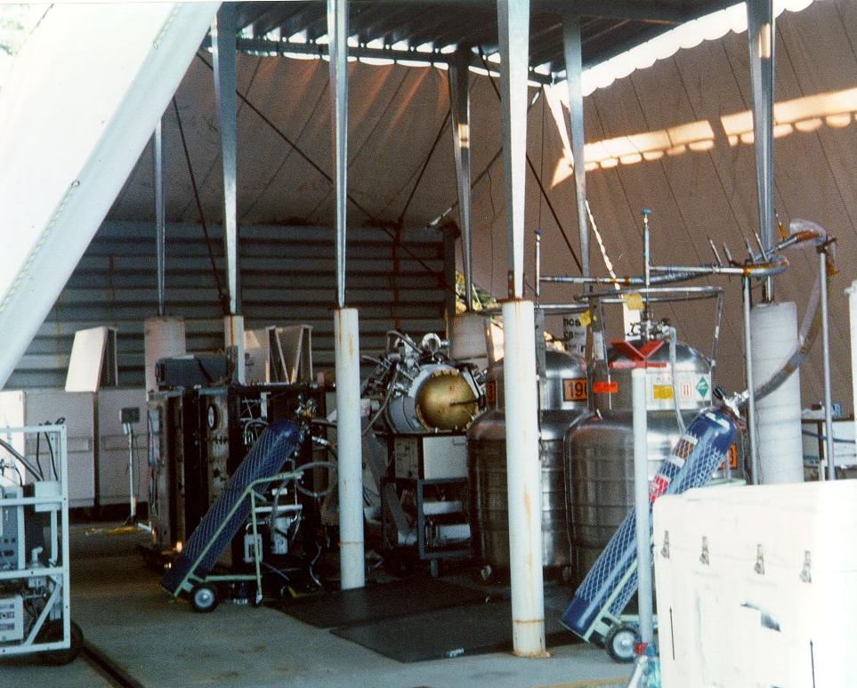
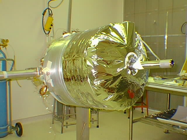
This photo shows the cryostat during hydrogen testing at Lockheed-Martin's Santa Cruz facility in July 1997. |
|
Close-up of the cryostat during hydrogen testing at Lockheed-Martin's Santa Cruz facility in July 1997. |
|
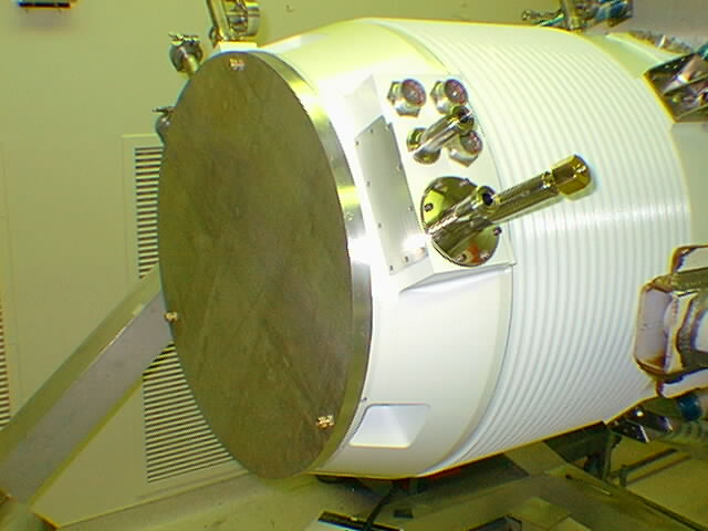
The assembled cryostat with the ETU aperture shade during bakeout. Photo taken July 7, 1997. |
|
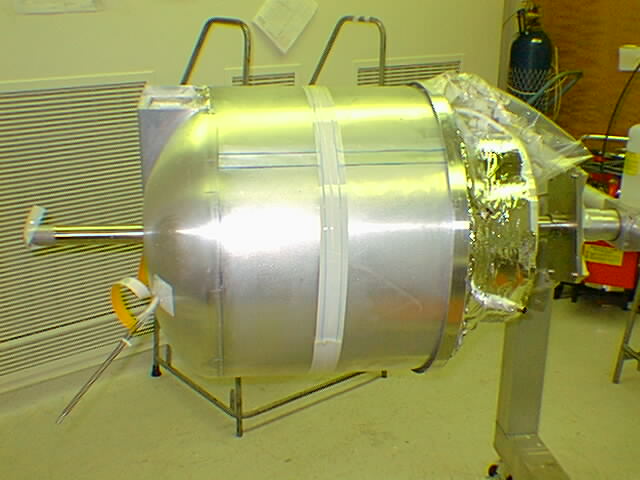
This photo, taken June 27, 1997, shows the WIRE cryostat during bakeout at Lockheed-Martin in Palo Alto, CA. |
|
An upright side view of the assembled cryostat without the front cover. Photo taken June 6, 1997. |
|
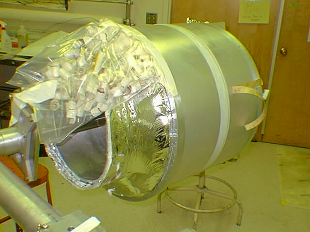
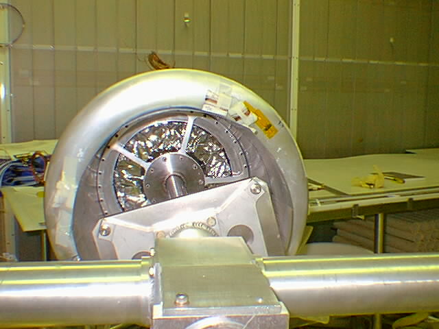
This photo, taken June 6, shows the forward aperture of the assembled cryostat without the front cover. |
|
This photo, taken February 12, 1997, shows a side view of the WIRE cryostat currently under assembly at Lockheed Martin in Palo Alto, CA. The forward aperture faces to the right in the photo; the aft dome of the second vapor cooled shield is to the left. The long dimension of the pictured hardware is about 30 inches. The primary vent line protrudes through the upper left portion of the aft dome. The ring visible at the right "shoulder" of the cryostat is the aluminum ring that connects the #3 composite support tube (installed, but hidden by the vapor cooled shield) to the #4 support tube (not yet installed). The central tube holding the cryostat is a fixture that will be removed later. |
|
This photo, taken February 12, 1997, shows the forward aperture of the cryostat currently under assembly at Lockheed Martin in Palo Alto, CA. The plastic bag holds instrumentation wiring. The cryostat assembly as shown has been built outward from the two inner tanks (not visible) to the second vapor-cooled shield seen in the photo. The ring located at the "shoulder" of the cryostat is the aluminum ring that connects the #3 composite support tube (installed, but not visible) to the #4 support tube (not yet installed). The central tube holding the cryostat is a fixture that will be removed later. |
|
This image shows the aft end of the cryostat following the installation and insulation of the aft dome. The center cylindrical tube is part of the assembly fixturing. Some instrumentation wiring can be seen near the front of the cryostat. Three composite support tubes will be attached to the middle of the cryostat secondary tank, building outward toward the vacuum shell. (06 December 1996) |
|
This view shows the forward (aperture) end of the cryostat looking into the central volume that will hold the telescope. The cylindrical beam in the center is an assembly fixture. The telescope-to-cryostat mounting flange is being used to hold the cryo-assembly on the assembly fixture. (21 November 1996) |
|
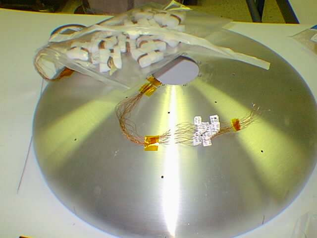
This image shows the cryostat aft dome prior to installation on the secondary tank. The wire bundles are for various ground and on-orbit documentation. |
See Photos of WIRE Telescope & Cryostat Assembly
Last Updated: 1/30/99