2MASS position reconstruction in the scan processing pipeline is divided into two primary tasks. The first task, accomplished by the Position-of-Frames (PosFrm) module, is the reconstruction of frame positions and the second, accomplished by the Position-of-Points (PosPts) module, is the reconstruction of point source positions. These are well separated in the 2MAPPS pipeline because relative frame positions are required before the multi-frame extractions, profile-fit photometry and band merging can occur. The final reconstructed point source positions, on the other hand, cannot be determined until after they occur.
i. Reconstruction of Frame Positions
By necessity, PosFrm uses single-frame extractions to tie the frames together. In order to minimize random walk, PosFrm simultaneously ties the frames to a set of absolute reference points, even as they are tied together. Thus, PosFrm frame positions are accurate in an absolute as well as relative sense. The absolute reference points are obtained from the U.S. Naval Observatory's ACT Reference Catalog. This catalog (988,758 stars) overcomes the short-baseline proper motion limitations of the Tycho catalog by combining it with the 100-year-baseline Astrographic Catalog.
During a normal survey scan, through a combination of scan rate and secondary mirror motion, the 2MASS telescope freezes the sky at 273 points along the scan. These are generally referred to as "frames", but herein they will be referred to with all caps as "FRAMES". For each FRAME, point source extractions are available for Read1 and Read2-Read1 for each of the three bands, yielding 6 lower case "frames" consisting of J1, J2, H1, H2, K1 and K2. It is PosFrm's task to bring all the frames together. Since scans are executed by displacing each FRAME one sixth of its width from the last, a single star could be show up in six FRAMES (36 frames). In order to be assured of 6-deep FRAME coverage, the offset is made a little less than one sixth of a FRAME width resulting in a small percentage of the scan covered by seven FRAMES (42 frames). The number of frames on which a single true source appears is quite significant. As will be shown later, it provides a powerful lever for tying the frames together.
PosFrm solves for the frame positions by minimizing a weighted sum of squares of the position differences between multiple frame observations of each common source and between frame observations and reference star positions. In order to end up with a set of LINEAR equations the problem is formulated to solve for small differences from a priori parameter estimates. Model parameters for which to solve were chosen to strike a balance between the fidelity of the model and limitations imposed by the minimum number of differences available per scan.
i.a. Preparations for Least-Squares Fit
Before proceeding to a more detailed description of PosFrm reconstruction it is first necessary to define some parameters and coordinate systems (see Table I). The first step toward an optimized solution is to express all single-frame extractions and reference stars in a common coordinate system. Since the combined pixels of the three detector arrays involved sweep out a narrow (~8.5' wide) near-great-circle path across the sky, the common system can be Cartesian without any significant loss of accuracy. That common system is referred to as the Universal scan (U-scan) system which has its origin at the center of the first FRAME and its y-axis running along the common scan path increasing to the north. What's needed is a set of coordinate transformations which bring the band-frame (B-frame) single-frame extraction positions available into the U-scan system. Discussion of these transformations will be delayed until section I-C, after additional parameters have been introduced.
Tying the frames to each other and to the sky requires knowledge of which frame-level extractions share a common source and which of those common sources can be matched to reference stars. A priori knowledge of the band-to-band relationships is sufficiently accurate to identify the extractions which share a common source. Matching to reference stars is not as straightforward since a priori knowledge of the absolute position is considerably worse than band-to-band knowledge. To accomplish this a Nominal scan (N-scan) system is defined such that the y-axis points precisely north along the of-date meridian, the x-axis points west and the origin is set by a priori knowledge. It's important to note that, once set, the N-scan system is precisely defined w.r.t. J2000; thus, no positional accuracy is lost by converting ACT positions to N-scan coordinates. If the a priori knowledge were perfect and the telescope scanned right along the of-date meridian, then the U-scan and N-scan systems would be coincident. Neither is true, but differences between the two systems are quite small. We're now in position to do a pattern match between the reference stars in N-scan coordinates and the 2MASS extractions in U-scan.
The matching is accomplished using a simple but effective approach referred to as a "two-peg pattern matcher". Two reference stars, well separated in-scan and well away from the scan edges, are selected as the "reference pegs". The task of the matcher is to find the corresponding pair of 2MASS extractions which will be referred to as "extraction pegs". All extractions within an uncertainty radius of each of the reference pegs are candidates for the extraction pegs. The pattern matcher walks through the possible pairs of candidate extraction pegs and performs a linear transformation (2 translation, 1 rotation and 1 scale [in-scan only]) to force the selected candidate extraction pegs to the reference pegs. The attempt is scored based on how many additional matches (<3") result from that transformation. For a correct selection of extraction pegs, the additional match count jumps far above the random match level. In the rare event that no pattern match is found among the extraction peg candidates, the algorithm selects new reference pegs and repeats. This technique is efficient for several reasons. Extraction peg candidates are prioritized based on magnitude and radial distance from the reference pegs. Once a pattern match is found the search can stop. The absolute pointing of the 2MASS telescopes is excellent, so the a priori positions are usually within about 10 arc-seconds. Once a pattern match is obtained, a 5 parameter linear transformation ( 2 translation, 1 rotation, 2 scale) is fitted using all 2MASS/reference matches. Using that transformation the reference stars can now be placed in the U-scan system.
i.b. Trimming to Workable Size
Given enough extractions, reference stars and computer resources, a five parameter linear fit for each frame would be ideal. Doing so would involve solving for five variables per frame (30 variables per FRAME) resulting in 8190 variables for a standard 273 FRAME survey scan. In order to reduce the scope of the problem to a more workable size, a number of carefully chosen simplifying assumptions were made. These simplifications involve moving some parameters to be solved from frame-level up to scan-level. These simplifications resulted in a parameter set reduced to 546 frame-level and 17 scan-level parameters, for a total of 563. While still large, the resulting set of 563 simultaneous equations has proved to provide consistently stable solutions over the wide array of source densities encountered.
Simplifying assumptions include the following:
1) H2 and K2 frame centers differ from J2 centers by constant translational offsets (DxJ2H, DyJ2H, DxJ2K, DyJ2K) over an entire scan, where:
                          DxJ2H = DxJ2H_0 + dDxJ2H
                          DyJ2H = DyJ2H_0 + dDyJ2H
                          DxJ2K = DxJ2K_0 + dDxJ2K
                          DyJ2K = DyJ2K_0 + dDyJ2K

      The parameters ending in "_0" are a priori estimates and the parameters
      beginning with "dD" are small adjustments to be solved for, providing
      4 of the 17 scan level parameters.
2) Read1 frame centers differ from Read2-Read1 frame centers of the same band by translational offsets (DxR1, DyR1) which vary linearly with frame number:
                 DxR1 = (mxR1_0 +dmxR1)*nf + (cxR1_0 +dcxR1)
                 DyR1 = (myR1_0 +dmyR1)*nf + (cyR1_0 +dcyR1)

      The parameters ending in "_0" are a priori estimates of the linear
      coefficients and those beginning with "dm" and "dc" are small
      small adjustments to be solved for, providing an additional 4
      scan-level parameters.  In these equations "nf" refers to frame number.
3) Rotation angles (TJ, TH, TK), cross-scan scale factors (SXJ, SXH, SXK) and in-scan scale factors (SYJ, SYH, SYK) of individual frames remain constant within each band over the entire scan.
                            TJ = TJ_0 + dTJ
                            TH = TH_0 + dTH
                            TK = TK_0 + dTK

                            SXJ = (1 + dSXJ)*SXJ_0
                            SXH = (1 + dSXH)*SXH_0
                            SXK = (1 + dSXK)*SXK_0

                            SYJ = (1 + dSYJ)*SYJ_0
                            SYH = (1 + dSYH)*SYH_0
                            SYK = (1 + dSYK)*SYK_0

      Parameters beginning with "T" are rotation angles and those
      beginning with "dT" are small rotation angle adjustments to be
      solved for.  Those beginning with "SX" and "SY" are cross-scan and
      in-scan scale factors, respectively.  As before, the parameters
      ending in "_0" are a priori estimates. The parameters beginning with
      "dS" are small adjustments to be solved.  Taken together these
      provide the remaining 9 scan-level parameters
In addition to the 17 scan-level parameters, there remain 546 frame-level parameters in a standard survey scan. These are the two translational adjustments (dxJ2n,dyJ2n) associated with each of the 273 J2 frame centers.
i.c. Solving for Adjustments
Table II lays out the equations needed to convert from B-frame to U-scan coordinates. The equations include all the small adjustment variables for which we would like to solve. Define "S" to be the sum of weighted differences squared for all combinations of all extractions associated with a common source regardless of type (J1, J2, H1, H2, K1, K2) or FRAME number. Add into "S" weighted differences squared between each matched reference star and every extraction to which it can be matched. Note that since every extraction is differenced from every other extraction of a common source the number of measurements goes up very rapidly. Finally add into "S" the sum of very lightly weighted differences squared where the differences are in fact changes w.r.t. the a priori frame-to-frame positions. This is added to handle an extreme case where no common source extractions exist to tie in one or more frames. The weighting is set low enough that it has no effect on the solution under normal circumstances. Take the partial derivative of "S" w.r.t. each of the 563 adjustment variables previously discussed and set to zero. This results in a large set of simultaneous linear equations which can then solved for the desired variables. The process just described is presented mathematically in Table III
The partials were setup to be solved symbolically using MAPLE (Maple V Release 3 for MS Windows by Waterloo Maple Software and the University of Waterloo), which was directed to output Fortran code. Note that the form of the partial varies with the terms within the summation depending on the combination of types being differenced (J1:J1, J1:J2, J1:H1, J1:H2...) as well as for each combination of type vs. reference star (J1:RS, J2:RS, H1:RS,...). Each combination was fed to MAPLE and the code output by Maple was then modified by a routine written specifically for the purpose to make it compatible with the rest of PosFrm. This process resulted in a number Fortran routines consisting of thousands of lines of machine generated code. The routines were thoroughly tested and proved to work very well indeed.
After all the small adjustments have been determined, they are used in the coordinate conversion equations from Table II to obtain U-scan positions for all the frame-level extractions used in the reconstruction. These data are used to verify that all six frame types have been brought successfully together over the entire scan. All extractions associated with a common source (up to 42 extractions/source) are merged together to generate the PosFrm Merged Point (PFMP) file. The merged point positions are also transformed from U-scan through N-scan to J2000 and these positions are carried in the PFMP file as well. Differences between the PFMP and ACT positions are monitored during processing for quality assurance.
Well after the aforementioned least-square equations were derived, coded and tested, it was discovered that the relative band-to-band positions can sometimes change by small amounts during the course of a single scan due to flexure in the camera or small motions of the arrays themselves. Modeling the band differences as linear with frame number, rather than constant, appeared a better way to go. Rather than go back to rederive, recode and retest, with associated time delays and risks, it was decided to add a separate linear fit for each band to minimize differences w.r.t. the PFMP positions obtained from the original solution.
ii. Reconstruction of Point Source Positions
After the Atlas Images are assembled using the frame positions as determined by PosFrm, point sources are detected from the Atlas Images and extracted using all available multi-frame, multi-band information. The resulting bandmerged sources are matched to the PFMP sources previously generated by PosFrm and already tied to the ACT. Using points in common between the two sets of merged sources, PosPts performs a single 5 parameter linear fit to remove any biases which might result from the two different extraction methods.
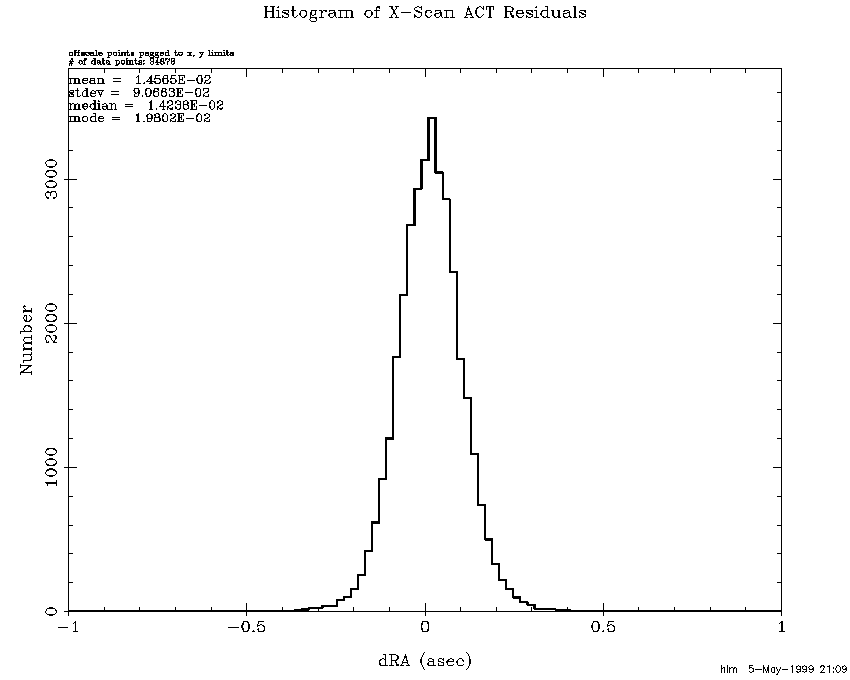
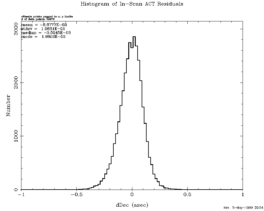
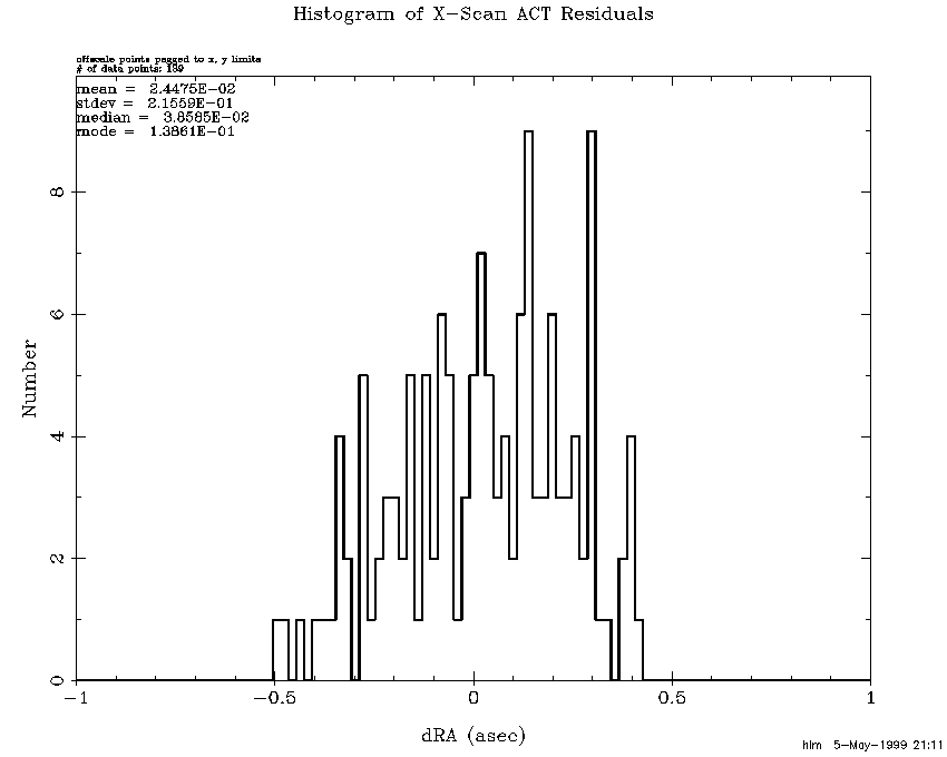
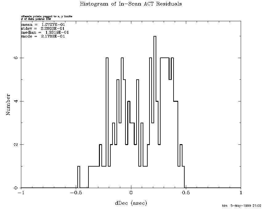
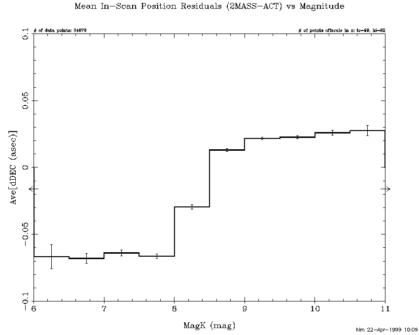
As a whole, the position results for this release are quite good, exceeding the 0.5 asec one-sigma requirement by a considerable margin. Figure 1 presents a histogram of RA differences (true angle) of 2MASS positions w.r.t. the corresponding ACT positions for all 3391 survey scans. Figure 2 histograms the Dec differences w.r.t. the ACT. Note that the sigmas are approximately 0.1 asec in both directions (slightly more in Dec and less in RA) with mean differences that are essentially zero. These histograms include data from 86 scans for which the number and/or distribution of ACT stars was insufficient to use them as reference stars. For these scans the USNOA catalog was used, resulting in reduced reconstruction accuracy. One measure of that reduction can be seen in residual histograms w.r.t. the few (but unused) ACT stars in the 86 scans. The RA differences are presented for these scans alone in Figure 3 and the Dec differences in Figure 4. Note that differences range out to 0.5 arc-second with sigmas which remain below a quarter arc-second. A magnitude dependent bias in Declination Figure 5 was discovered during preparations for this release. It appears to be due to differences in the way Read1-only verses Read2-Read1 sources are handled in the pipeline and may account for the increased in-scan dispersions. It is expected that it can be removed in a future release, further improving the accuracy.
|
|
|
|
| Figure 1 | Figure 2 | Figure 3 |
|
 |
| Figure 4 | Figure 5 |
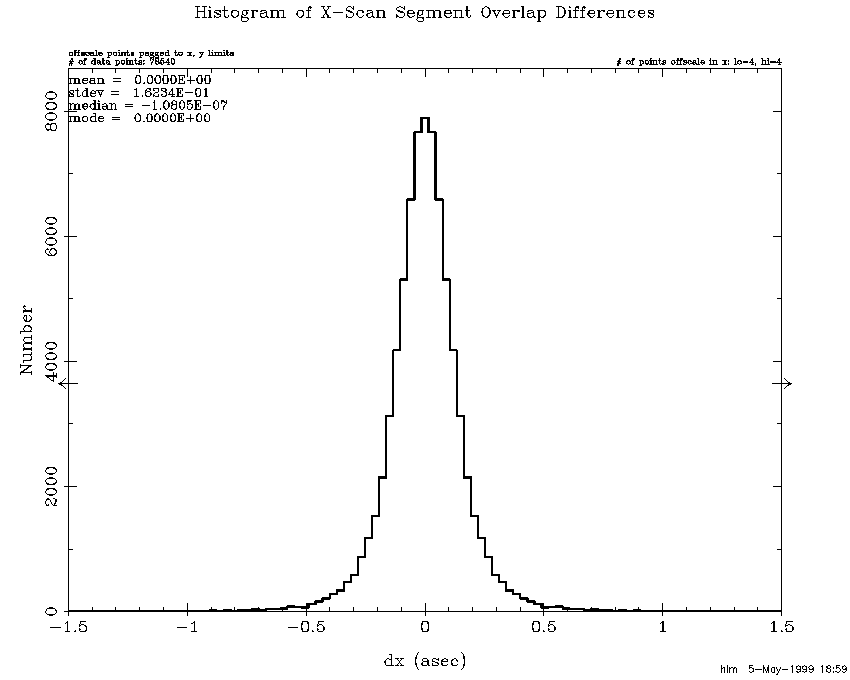
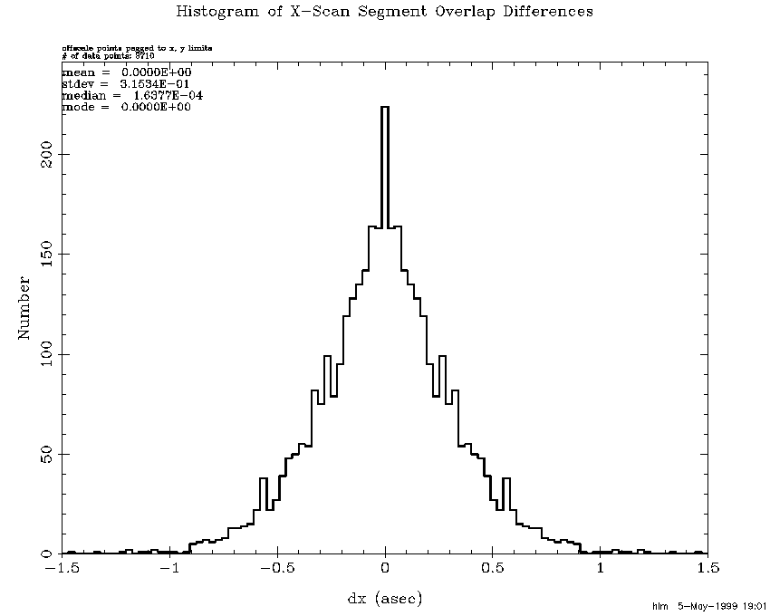
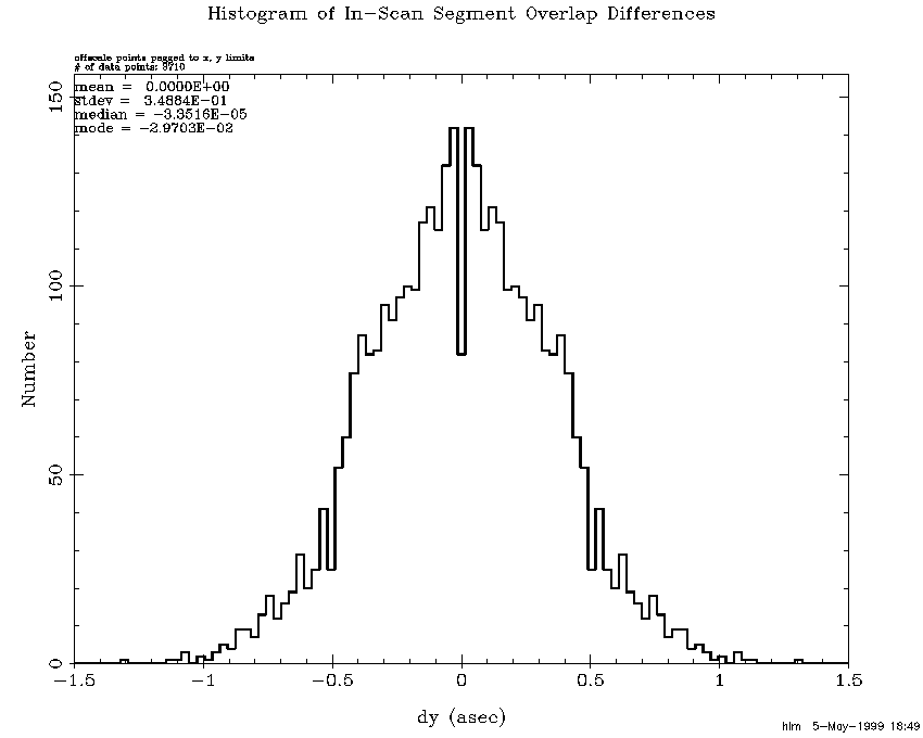
The fact that 2MASS positions closely match the ACT positions does not by itself guarantee that all is well. One would expect position errors to grow between ACT stars due to random walk. Position differences within scan overlaps reveal how consistent the reconstructions are. Overlap consistency combined with ACT consistency makes a very strong case. Although each step of a "random walk" is, of course, random the resulting error can grow systematically for long periods. In order to track these deviations, each scan was broken down into 1/2 degree Dec segments and average overlap position differences were computed for each segment. Figure 6 histograms cross-scan segment differences for the entire release and Figure 7 histograms the corresponding in-scan differences. Note that the cross-scan sigma is 0.16 asec which with the square-root of 2 correction reduces to 0.12 asec. The corresponding numbers of the in-scan overlaps are 0.19 and 0.13 asec. It is obvious from these histograms that the tails are longer than those of a Gaussian distribution. The long tails are primarily the result of long periods without ACT stars. Figure 8 and Figure 9 repeat the same plots for only the 86 scans without ACT reconstructions. After the square-root of 2 correction the cross-scan and in-scan sigmas are 0.22 and 0.25 asec, which are very consistent with the ACT residuals for these scans.
|
 |
| Figure 6 | Figure 7 |
|
 |
| Figure 8 | Figure 9 |
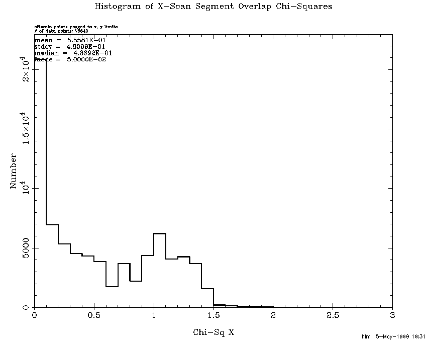
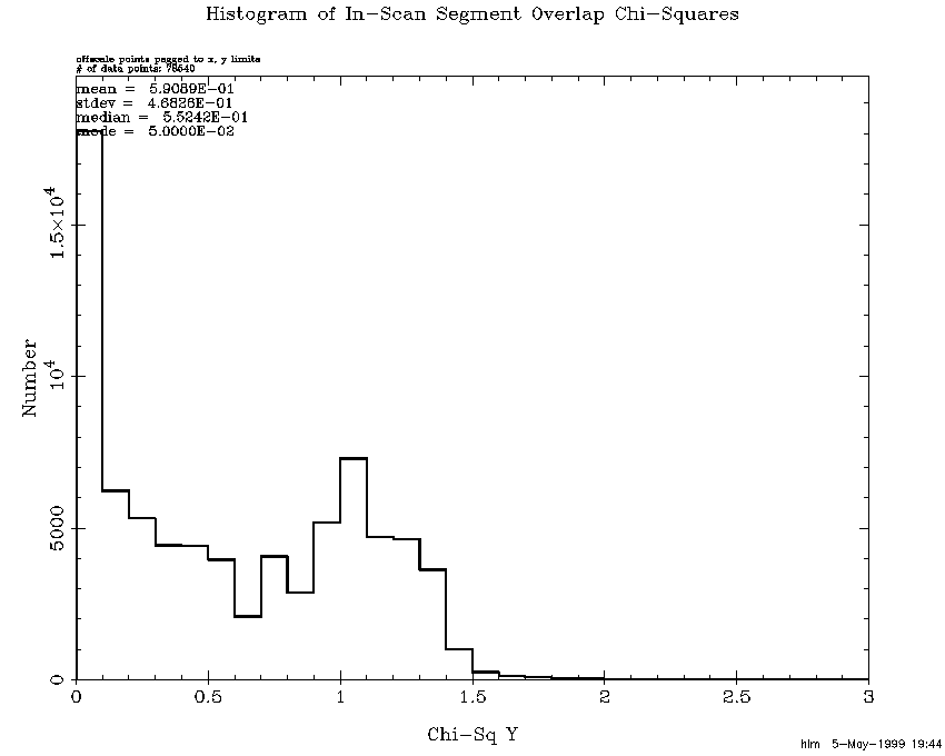
By analyzing chi-squares for the overlap differences, uncertainties have been adjusted to reflect the problem areas. The same technique described previously in Position Uncertainty Adjustments for 971116n was used with a couple of exceptions. Variance factors were allowed to go down to 0.1, and chi-squares were not forced down to one by upping the sigmas on the last iteration. A floor of 0.1 asec was, however, applied to the sigmas in both directions at the end. Figure 10 histograms the resulting cross-scan overlap chi-squares for the entire release, and Figure 11 presents the in-scan chi-squares. The distributions are rather unusual in that the frequency goes back up around one and then drops off almost completely by 1.5. This is presumably due to the algorithm trying to drive them to one. For this early release it was intended that the sigmas be somewhat conservative and these figures demonstrate that they are.
|
 |
| Figure 10 | Figure 11 |