A detailed description of the 2MASS camera optical design
appears in Milligan et al. (1996, SPIE Proceedings Volume
2863, p2).
i. Cryostat and Optical Configuration
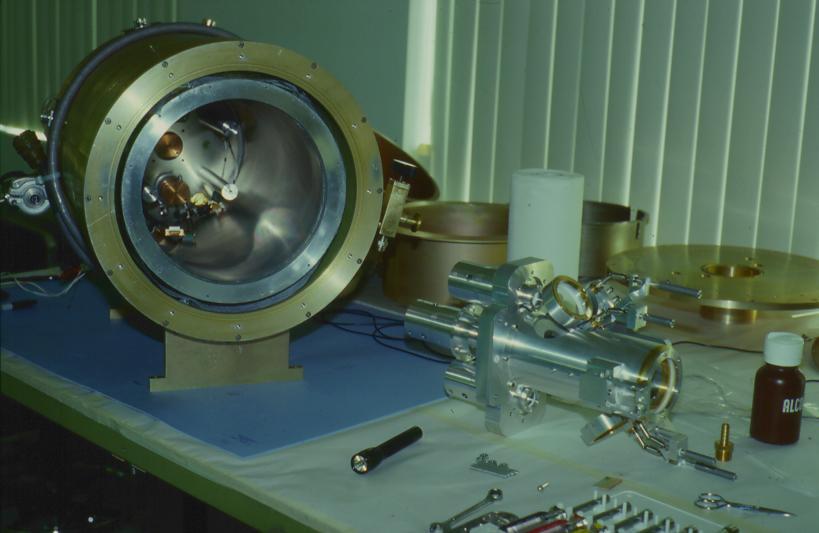
Each 2MASS camera consists of a liquid nitrogen cryostat (Figure 1, below) which
contains three NICMOS3 arrays. A raytrace (Figure 2, below)
of the system shows that each array views the same region of the sky
via beamsplitting dichroics. The light passes through both dichroics
to the Ks-band array. The first dichroic
reflection feeds the light to
the J-band array. All three optical paths share the same first element
which lies behind a cryogenic field stop. Each optical path has six
other lenses. This set of six lenses is identical for each band. The
lenses are composed of water-free fused silica (Infrasil) or calcium
fluoride. All lens surfaces are spherical. All optical elements are
anti-reflection coated and the integrated optical assembly transmits
~80% of the incident light. A band-limiting interference filter
located near a pupil image establishes the system bandpass.
The 2MASS bandpasses are:
1. Facilities
b. Camera and Detectors
| J-band | 1.11 - 1.36* microns |
| H-band | 1.50 - 1.80 microns |
| Ks-band | 2.00 - 2.32 microns |
The detector quantum efficiency, the anti-reflection coatings, and transmission of the dichroics, window, and optical elements are relatively flat across the bandpasses, so the band response functions are believed to be square to a good approximation. These values are all based on manufacturer's specifications. The completed camera optical assembly (Figure 3, below) forms a modular unit which attaches to the cryostat (Figure 1, below) cold plate adjacent to the three detector arrays.
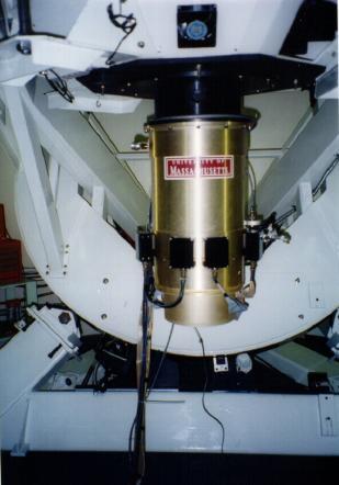
The optics relay approximately 90% of the energy of a laboratory point source onto one 40 micron NICMOS3 pixel. When mounted on the 2MASS telescopes (Figure 4, below) each pixel subtends approximately 2.0" on the sky. Platescale varies by <1% between the three bands.
ii. Optical Response Functions
iii. Electronics
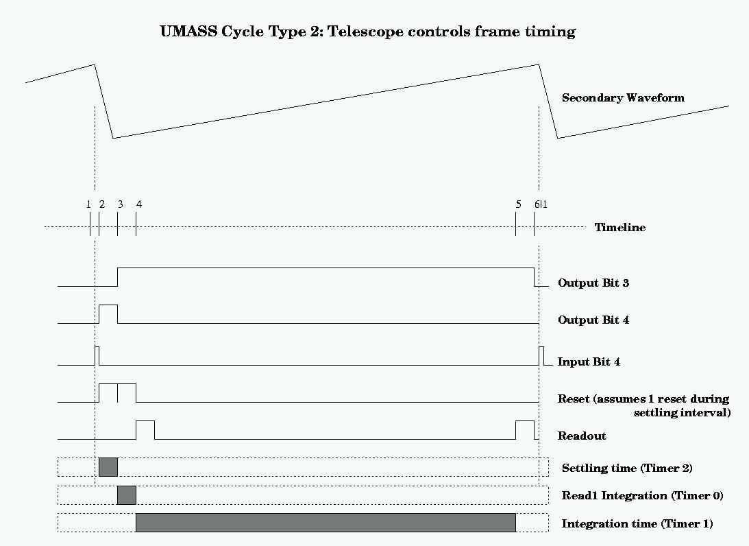
The 2MASS readout electronics sample each pixel with 16-bit precision with a pixel dwell time of 3.0 microseconds. A complete readout of the array requires approximately 51 milliseconds. In order to preserve a constant integration time spatially across the array, the reset cycle clocks with precisely the same timing as a readout cycle. A 2MASS frame results from the following sequence of events:
The gain of the 2MASS electronics is approximately 8 electrons per analog-to-digital count. The array bias voltage has been set to 1.00 V to produce a dynamic range of 50,000 counts or 400,000 electrons. The system read noise in a doubly correlated difference is 5 counts or 40 electrons. In the standard 1.3 sec integration, sky photon noise dominates the read noise in all three band, although under extremely low-airglow conditions the read noise and photon noise in the J-band become nearly equal.
|
|
|
|
| Figure 1 | Figure 2 | Figure 3 |
|
 |
| Figure 4 | Figure 5 |